LnRiLWdhbGxlcnkgdWx7bGlzdC1zdHlsZTpub25lO21hcmdpbjowIDAgMS41ZW0gMDtwYWRkaW5nOjB9LnRiLWdhbGxlcnlfX2NlbGx7bWFyZ2luOjAgIWltcG9ydGFudDtwb3NpdGlvbjpyZWxhdGl2ZX0udGItZ2FsbGVyeS0tZ3JpZHtkaXNwbGF5OmdyaWQ7Z3JpZC1hdXRvLXJvd3M6YXV0byAhaW1wb3J0YW50fS50Yi1nYWxsZXJ5LS1ncmlkOm5vdCgudGItZ2FsbGVyeS0tZ3JpZC0tbm9jcm9wKSAudGItYnJpY2tfX2NvbnRlbnR7aGVpZ2h0OjEwMCU7cG9zaXRpb246YWJzb2x1dGU7dG9wOjB9LnRiLWdhbGxlcnktLWdyaWQ6bm90KC50Yi1nYWxsZXJ5LS1ncmlkLS1ub2Nyb3ApIC50Yi1nYWxsZXJ5X19jZWxse2dyaWQtcm93LWVuZDp1bnNldCAhaW1wb3J0YW50O3Bvc2l0aW9uOnJlbGF0aXZlfS50Yi1nYWxsZXJ5LS1ncmlkOm5vdCgudGItZ2FsbGVyeS0tZ3JpZC0tbm9jcm9wKSAudGItZ2FsbGVyeV9fY2VsbDo6YmVmb3Jle2NvbnRlbnQ6IiI7ZGlzcGxheTppbmxpbmUtYmxvY2s7cGFkZGluZy1ib3R0b206MTAwJX0udGItZ2FsbGVyeS0tZ3JpZDpub3QoLnRiLWdhbGxlcnktLWdyaWQtLW5vY3JvcCkgLnRiLWdhbGxlcnlfX2NlbGw6Om1hcmtlcntjb250ZW50OiIifS50Yi1nYWxsZXJ5LS1ncmlkOm5vdCgudGItZ2FsbGVyeS0tZ3JpZC0tbm9jcm9wKSBpbWd7d2lkdGg6MTAwJTtoZWlnaHQ6MTAwJTstby1vYmplY3QtZml0OmNvdmVyO29iamVjdC1maXQ6Y292ZXJ9LnRiLWdhbGxlcnktLWdyaWQtLW5vY3JvcCBpbWd7aGVpZ2h0OmF1dG8gIWltcG9ydGFudDt3aWR0aDphdXRvICFpbXBvcnRhbnR9LnRiLWdhbGxlcnktLWdyaWQtLW5vY3JvcCAudGItZ2FsbGVyeV9fY2VsbHthbGlnbi1zZWxmOmVuZH0udGItZ2FsbGVyeS0tZ3JpZC0tbm9jcm9wIC50Yi1icmlja19fY29udGVudHtoZWlnaHQ6MTAwJX0udGItZ2FsbGVyeS0tY29sbGFnZXtkaXNwbGF5OmdyaWQ7Z3JpZC10ZW1wbGF0ZS1jb2x1bW5zOnJlcGVhdCgxMiwgMWZyKX0udGItZ2FsbGVyeS0tY29sbGFnZSAudGItYnJpY2tfX2NvbnRlbnR7aGVpZ2h0OjEwMCV9LnRiLWdhbGxlcnktLWNvbGxhZ2UgaW1ne2hlaWdodDoxMDAlICFpbXBvcnRhbnR9LnRiLWdhbGxlcnktLW1hc29ucnl7ZGlzcGxheTpncmlkO2dyaWQtcm93LWdhcDowO2dyaWQtYXV0by1yb3dzOjFweDtvcGFjaXR5OjB9LnRiLWdhbGxlcnktLW1hc29ucnkgLnRiLWJyaWNrX19jb250ZW50e3Bvc2l0aW9uOnJlbGF0aXZlfS50Yi1nYWxsZXJ5LS1tYXNvbnJ5IC50Yi1icmlja19fY29udGVudCBpbWcsLnRiLWdhbGxlcnktLW1hc29ucnkgLnRiLWJyaWNrX19jb250ZW50IGlmcmFtZSwudGItZ2FsbGVyeS0tbWFzb25yeSAudGItYnJpY2tfX2NvbnRlbnQgdmlkZW97LW8tb2JqZWN0LWZpdDpjb3ZlcjtvYmplY3QtZml0OmNvdmVyO3dpZHRoOjEwMCUgIWltcG9ydGFudDtkaXNwbGF5OmJsb2NrfS50Yi1nYWxsZXJ5X19jYXB0aW9ue3Bvc2l0aW9uOmFic29sdXRlO2JvdHRvbTowO3dpZHRoOjEwMCU7YmFja2dyb3VuZDpyZ2JhKDI1NSwyNTUsMjU1LDAuNik7cGFkZGluZzo1cHggMnB4O3RleHQtYWxpZ246Y2VudGVyO2NvbG9yOiMzMzN9LnRiLWdhbGxlcnlfX2NhcHRpb246ZW1wdHl7YmFja2dyb3VuZDp0cmFuc3BhcmVudCAhaW1wb3J0YW50fS50Yi1nYWxsZXJ5IC50Yi1icmlja19fY29udGVudCBmaWd1cmV7aGVpZ2h0OjEwMCV9LnRiLWdhbGxlcnkgaW1ne3dpZHRoOjEwMCU7aGVpZ2h0OjEwMCU7LW8tb2JqZWN0LWZpdDpjb3ZlcjtvYmplY3QtZml0OmNvdmVyO3ZlcnRpY2FsLWFsaWduOmJvdHRvbX0jbGVmdC1hcmVhIHVsLnRiLWdhbGxlcnl7bGlzdC1zdHlsZS10eXBlOm5vbmU7cGFkZGluZzowfSAudGItZ2FsbGVyeVtkYXRhLXRvb2xzZXQtYmxvY2tzLWdhbGxlcnk9Ijc4NmNmMjRkZjMyYmM5M2U4YjQ2NzRlOTM2OGY4NmZmIl0gLnRiLWdhbGxlcnktLWNvbGxhZ2UgeyBncmlkLWNvbHVtbi1nYXA6IDE1cHg7Z3JpZC1yb3ctZ2FwOiAxNXB4O2dyaWQtYXV0by1yb3dzOiA4My4zMzMzMzMzMzMzMzNweCB9IC50Yi1nYWxsZXJ5W2RhdGEtdG9vbHNldC1ibG9ja3MtZ2FsbGVyeT0iNzg2Y2YyNGRmMzJiYzkzZThiNDY3NGU5MzY4Zjg2ZmYiXSAudGItZ2FsbGVyeS0tY29sbGFnZSBsaTpudGgtY2hpbGQoNG4gKyAxKSB7IGdyaWQtYXJlYTogIGF1dG8gLyBhdXRvIC8gc3BhbiA0IC8gc3BhbiA4OyB9IC50Yi1nYWxsZXJ5W2RhdGEtdG9vbHNldC1ibG9ja3MtZ2FsbGVyeT0iNzg2Y2YyNGRmMzJiYzkzZThiNDY3NGU5MzY4Zjg2ZmYiXSAudGItZ2FsbGVyeS0tY29sbGFnZSBsaTpudGgtY2hpbGQoNG4gKyAyKSB7IGdyaWQtYXJlYTogIGF1dG8gLyBhdXRvIC8gc3BhbiA0IC8gc3BhbiA0OyB9IC50Yi1nYWxsZXJ5W2RhdGEtdG9vbHNldC1ibG9ja3MtZ2FsbGVyeT0iNzg2Y2YyNGRmMzJiYzkzZThiNDY3NGU5MzY4Zjg2ZmYiXSAudGItZ2FsbGVyeS0tY29sbGFnZSBsaTpudGgtY2hpbGQoNG4gKyAzKSB7IGdyaWQtYXJlYTogIGF1dG8gLyBhdXRvIC8gc3BhbiAyIC8gc3BhbiA0OyB9IC50Yi1nYWxsZXJ5W2RhdGEtdG9vbHNldC1ibG9ja3MtZ2FsbGVyeT0iNzg2Y2YyNGRmMzJiYzkzZThiNDY3NGU5MzY4Zjg2ZmYiXSAudGItZ2FsbGVyeS0tY29sbGFnZSBsaTpudGgtY2hpbGQoNG4gKyA0KSB7IGdyaWQtYXJlYTogIGF1dG8gLyBhdXRvIC8gc3BhbiAyIC8gc3BhbiA4OyB9IC50Yi1ncmlkLC50Yi1ncmlkPi5ibG9jay1lZGl0b3ItaW5uZXItYmxvY2tzPi5ibG9jay1lZGl0b3ItYmxvY2stbGlzdF9fbGF5b3V0e2Rpc3BsYXk6Z3JpZDtncmlkLXJvdy1nYXA6MjVweDtncmlkLWNvbHVtbi1nYXA6MjVweH0udGItZ3JpZC1pdGVte2JhY2tncm91bmQ6I2QzOGEwMztwYWRkaW5nOjMwcHh9LnRiLWdyaWQtY29sdW1ue2ZsZXgtd3JhcDp3cmFwfS50Yi1ncmlkLWNvbHVtbj4qe3dpZHRoOjEwMCV9LnRiLWdyaWQtY29sdW1uLnRiLWdyaWQtYWxpZ24tdG9we3dpZHRoOjEwMCU7ZGlzcGxheTpmbGV4O2FsaWduLWNvbnRlbnQ6ZmxleC1zdGFydH0udGItZ3JpZC1jb2x1bW4udGItZ3JpZC1hbGlnbi1jZW50ZXJ7d2lkdGg6MTAwJTtkaXNwbGF5OmZsZXg7YWxpZ24tY29udGVudDpjZW50ZXJ9LnRiLWdyaWQtY29sdW1uLnRiLWdyaWQtYWxpZ24tYm90dG9te3dpZHRoOjEwMCU7ZGlzcGxheTpmbGV4O2FsaWduLWNvbnRlbnQ6ZmxleC1lbmR9IC53cC1ibG9jay10b29sc2V0LWJsb2Nrcy1ncmlkLnRiLWdyaWRbZGF0YS10b29sc2V0LWJsb2Nrcy1ncmlkPSJlN2I5YmJlZjNjMWM4ZjdlMTFkNGZjZmJjNWViNDdiNCJdIHsgZ3JpZC10ZW1wbGF0ZS1jb2x1bW5zOiBtaW5tYXgoMCwgMC41ZnIpIG1pbm1heCgwLCAwLjVmcik7Z3JpZC1hdXRvLWZsb3c6IHJvdyB9IC53cC1ibG9jay10b29sc2V0LWJsb2Nrcy1ncmlkLnRiLWdyaWRbZGF0YS10b29sc2V0LWJsb2Nrcy1ncmlkPSJlN2I5YmJlZjNjMWM4ZjdlMTFkNGZjZmJjNWViNDdiNCJdID4gLnRiLWdyaWQtY29sdW1uOm50aC1vZi10eXBlKDJuICsgMSkgeyBncmlkLWNvbHVtbjogMSB9IC53cC1ibG9jay10b29sc2V0LWJsb2Nrcy1ncmlkLnRiLWdyaWRbZGF0YS10b29sc2V0LWJsb2Nrcy1ncmlkPSJlN2I5YmJlZjNjMWM4ZjdlMTFkNGZjZmJjNWViNDdiNCJdID4gLnRiLWdyaWQtY29sdW1uOm50aC1vZi10eXBlKDJuICsgMikgeyBncmlkLWNvbHVtbjogMiB9ICAud3AtYmxvY2stdG9vbHNldC1ibG9ja3MtZ3JpZC1jb2x1bW4udGItZ3JpZC1jb2x1bW5bZGF0YS10b29sc2V0LWJsb2Nrcy1ncmlkLWNvbHVtbj0iMzAzNGZiZTg4NmMxMTA1NGU5NWI0NmIwOWQzZTQxMTIiXSB7IGRpc3BsYXk6IGZsZXg7IH0gICAudGItaW1hZ2V7cG9zaXRpb246cmVsYXRpdmU7dHJhbnNpdGlvbjp0cmFuc2Zvcm0gMC4yNXMgZWFzZX0ud3AtYmxvY2staW1hZ2UgLnRiLWltYWdlLmFsaWduY2VudGVye21hcmdpbi1sZWZ0OmF1dG87bWFyZ2luLXJpZ2h0OmF1dG99LnRiLWltYWdlIGltZ3ttYXgtd2lkdGg6MTAwJTtoZWlnaHQ6YXV0bzt3aWR0aDphdXRvO3RyYW5zaXRpb246dHJhbnNmb3JtIDAuMjVzIGVhc2V9LnRiLWltYWdlIC50Yi1pbWFnZS1jYXB0aW9uLWZpdC10by1pbWFnZXtkaXNwbGF5OnRhYmxlfS50Yi1pbWFnZSAudGItaW1hZ2UtY2FwdGlvbi1maXQtdG8taW1hZ2UgLnRiLWltYWdlLWNhcHRpb257ZGlzcGxheTp0YWJsZS1jYXB0aW9uO2NhcHRpb24tc2lkZTpib3R0b219IC53cC1ibG9jay1pbWFnZS50Yi1pbWFnZVtkYXRhLXRvb2xzZXQtYmxvY2tzLWltYWdlPSJmYzQ5YTMxZThlNGY5MDQyNzNjY2ViNTEzODdlYWE1NyJdIHsgbWF4LXdpZHRoOiAxMDAlOyB9IEBtZWRpYSBvbmx5IHNjcmVlbiBhbmQgKG1heC13aWR0aDogNzgxcHgpIHsgLnRiLWdhbGxlcnkgdWx7bGlzdC1zdHlsZTpub25lO21hcmdpbjowIDAgMS41ZW0gMDtwYWRkaW5nOjB9LnRiLWdhbGxlcnlfX2NlbGx7bWFyZ2luOjAgIWltcG9ydGFudDtwb3NpdGlvbjpyZWxhdGl2ZX0udGItZ2FsbGVyeS0tZ3JpZHtkaXNwbGF5OmdyaWQ7Z3JpZC1hdXRvLXJvd3M6YXV0byAhaW1wb3J0YW50fS50Yi1nYWxsZXJ5LS1ncmlkOm5vdCgudGItZ2FsbGVyeS0tZ3JpZC0tbm9jcm9wKSAudGItYnJpY2tfX2NvbnRlbnR7aGVpZ2h0OjEwMCU7cG9zaXRpb246YWJzb2x1dGU7dG9wOjB9LnRiLWdhbGxlcnktLWdyaWQ6bm90KC50Yi1nYWxsZXJ5LS1ncmlkLS1ub2Nyb3ApIC50Yi1nYWxsZXJ5X19jZWxse2dyaWQtcm93LWVuZDp1bnNldCAhaW1wb3J0YW50O3Bvc2l0aW9uOnJlbGF0aXZlfS50Yi1nYWxsZXJ5LS1ncmlkOm5vdCgudGItZ2FsbGVyeS0tZ3JpZC0tbm9jcm9wKSAudGItZ2FsbGVyeV9fY2VsbDo6YmVmb3Jle2NvbnRlbnQ6IiI7ZGlzcGxheTppbmxpbmUtYmxvY2s7cGFkZGluZy1ib3R0b206MTAwJX0udGItZ2FsbGVyeS0tZ3JpZDpub3QoLnRiLWdhbGxlcnktLWdyaWQtLW5vY3JvcCkgLnRiLWdhbGxlcnlfX2NlbGw6Om1hcmtlcntjb250ZW50OiIifS50Yi1nYWxsZXJ5LS1ncmlkOm5vdCgudGItZ2FsbGVyeS0tZ3JpZC0tbm9jcm9wKSBpbWd7d2lkdGg6MTAwJTtoZWlnaHQ6MTAwJTstby1vYmplY3QtZml0OmNvdmVyO29iamVjdC1maXQ6Y292ZXJ9LnRiLWdhbGxlcnktLWdyaWQtLW5vY3JvcCBpbWd7aGVpZ2h0OmF1dG8gIWltcG9ydGFudDt3aWR0aDphdXRvICFpbXBvcnRhbnR9LnRiLWdhbGxlcnktLWdyaWQtLW5vY3JvcCAudGItZ2FsbGVyeV9fY2VsbHthbGlnbi1zZWxmOmVuZH0udGItZ2FsbGVyeS0tZ3JpZC0tbm9jcm9wIC50Yi1icmlja19fY29udGVudHtoZWlnaHQ6MTAwJX0udGItZ2FsbGVyeS0tY29sbGFnZXtkaXNwbGF5OmdyaWQ7Z3JpZC10ZW1wbGF0ZS1jb2x1bW5zOnJlcGVhdCgxMiwgMWZyKX0udGItZ2FsbGVyeS0tY29sbGFnZSAudGItYnJpY2tfX2NvbnRlbnR7aGVpZ2h0OjEwMCV9LnRiLWdhbGxlcnktLWNvbGxhZ2UgaW1ne2hlaWdodDoxMDAlICFpbXBvcnRhbnR9LnRiLWdhbGxlcnktLW1hc29ucnl7ZGlzcGxheTpncmlkO2dyaWQtcm93LWdhcDowO2dyaWQtYXV0by1yb3dzOjFweDtvcGFjaXR5OjB9LnRiLWdhbGxlcnktLW1hc29ucnkgLnRiLWJyaWNrX19jb250ZW50e3Bvc2l0aW9uOnJlbGF0aXZlfS50Yi1nYWxsZXJ5LS1tYXNvbnJ5IC50Yi1icmlja19fY29udGVudCBpbWcsLnRiLWdhbGxlcnktLW1hc29ucnkgLnRiLWJyaWNrX19jb250ZW50IGlmcmFtZSwudGItZ2FsbGVyeS0tbWFzb25yeSAudGItYnJpY2tfX2NvbnRlbnQgdmlkZW97LW8tb2JqZWN0LWZpdDpjb3ZlcjtvYmplY3QtZml0OmNvdmVyO3dpZHRoOjEwMCUgIWltcG9ydGFudDtkaXNwbGF5OmJsb2NrfS50Yi1nYWxsZXJ5X19jYXB0aW9ue3Bvc2l0aW9uOmFic29sdXRlO2JvdHRvbTowO3dpZHRoOjEwMCU7YmFja2dyb3VuZDpyZ2JhKDI1NSwyNTUsMjU1LDAuNik7cGFkZGluZzo1cHggMnB4O3RleHQtYWxpZ246Y2VudGVyO2NvbG9yOiMzMzN9LnRiLWdhbGxlcnlfX2NhcHRpb246ZW1wdHl7YmFja2dyb3VuZDp0cmFuc3BhcmVudCAhaW1wb3J0YW50fS50Yi1nYWxsZXJ5IC50Yi1icmlja19fY29udGVudCBmaWd1cmV7aGVpZ2h0OjEwMCV9LnRiLWdhbGxlcnkgaW1ne3dpZHRoOjEwMCU7aGVpZ2h0OjEwMCU7LW8tb2JqZWN0LWZpdDpjb3ZlcjtvYmplY3QtZml0OmNvdmVyO3ZlcnRpY2FsLWFsaWduOmJvdHRvbX0jbGVmdC1hcmVhIHVsLnRiLWdhbGxlcnl7bGlzdC1zdHlsZS10eXBlOm5vbmU7cGFkZGluZzowfSAudGItZ2FsbGVyeVtkYXRhLXRvb2xzZXQtYmxvY2tzLWdhbGxlcnk9Ijc4NmNmMjRkZjMyYmM5M2U4YjQ2NzRlOTM2OGY4NmZmIl0gLnRiLWdhbGxlcnktLWNvbGxhZ2UgbGk6bnRoLWNoaWxkKDNuICsgMSkgeyBncmlkLWFyZWE6ICBhdXRvIC8gYXV0byAvIHNwYW4gNCAvIHNwYW4gODsgfSAudGItZ2FsbGVyeVtkYXRhLXRvb2xzZXQtYmxvY2tzLWdhbGxlcnk9Ijc4NmNmMjRkZjMyYmM5M2U4YjQ2NzRlOTM2OGY4NmZmIl0gLnRiLWdhbGxlcnktLWNvbGxhZ2UgbGk6bnRoLWNoaWxkKDNuICsgMikgeyBncmlkLWFyZWE6ICBhdXRvIC8gYXV0byAvIHNwYW4gNCAvIHNwYW4gNDsgfSAudGItZ2FsbGVyeVtkYXRhLXRvb2xzZXQtYmxvY2tzLWdhbGxlcnk9Ijc4NmNmMjRkZjMyYmM5M2U4YjQ2NzRlOTM2OGY4NmZmIl0gLnRiLWdhbGxlcnktLWNvbGxhZ2UgbGk6bnRoLWNoaWxkKDNuICsgMykgeyBncmlkLWFyZWE6ICBhdXRvIC8gYXV0byAvIHNwYW4gMiAvIHNwYW4gMTI7IH0gLnRiLWdyaWQsLnRiLWdyaWQ+LmJsb2NrLWVkaXRvci1pbm5lci1ibG9ja3M+LmJsb2NrLWVkaXRvci1ibG9jay1saXN0X19sYXlvdXR7ZGlzcGxheTpncmlkO2dyaWQtcm93LWdhcDoyNXB4O2dyaWQtY29sdW1uLWdhcDoyNXB4fS50Yi1ncmlkLWl0ZW17YmFja2dyb3VuZDojZDM4YTAzO3BhZGRpbmc6MzBweH0udGItZ3JpZC1jb2x1bW57ZmxleC13cmFwOndyYXB9LnRiLWdyaWQtY29sdW1uPip7d2lkdGg6MTAwJX0udGItZ3JpZC1jb2x1bW4udGItZ3JpZC1hbGlnbi10b3B7d2lkdGg6MTAwJTtkaXNwbGF5OmZsZXg7YWxpZ24tY29udGVudDpmbGV4LXN0YXJ0fS50Yi1ncmlkLWNvbHVtbi50Yi1ncmlkLWFsaWduLWNlbnRlcnt3aWR0aDoxMDAlO2Rpc3BsYXk6ZmxleDthbGlnbi1jb250ZW50OmNlbnRlcn0udGItZ3JpZC1jb2x1bW4udGItZ3JpZC1hbGlnbi1ib3R0b217d2lkdGg6MTAwJTtkaXNwbGF5OmZsZXg7YWxpZ24tY29udGVudDpmbGV4LWVuZH0gLndwLWJsb2NrLXRvb2xzZXQtYmxvY2tzLWdyaWQudGItZ3JpZFtkYXRhLXRvb2xzZXQtYmxvY2tzLWdyaWQ9ImU3YjliYmVmM2MxYzhmN2UxMWQ0ZmNmYmM1ZWI0N2I0Il0geyBncmlkLXRlbXBsYXRlLWNvbHVtbnM6IG1pbm1heCgwLCAwLjVmcikgbWlubWF4KDAsIDAuNWZyKTtncmlkLWF1dG8tZmxvdzogcm93IH0gLndwLWJsb2NrLXRvb2xzZXQtYmxvY2tzLWdyaWQudGItZ3JpZFtkYXRhLXRvb2xzZXQtYmxvY2tzLWdyaWQ9ImU3YjliYmVmM2MxYzhmN2UxMWQ0ZmNmYmM1ZWI0N2I0Il0gPiAudGItZ3JpZC1jb2x1bW46bnRoLW9mLXR5cGUoMm4gKyAxKSB7IGdyaWQtY29sdW1uOiAxIH0gLndwLWJsb2NrLXRvb2xzZXQtYmxvY2tzLWdyaWQudGItZ3JpZFtkYXRhLXRvb2xzZXQtYmxvY2tzLWdyaWQ9ImU3YjliYmVmM2MxYzhmN2UxMWQ0ZmNmYmM1ZWI0N2I0Il0gPiAudGItZ3JpZC1jb2x1bW46bnRoLW9mLXR5cGUoMm4gKyAyKSB7IGdyaWQtY29sdW1uOiAyIH0gIC53cC1ibG9jay10b29sc2V0LWJsb2Nrcy1ncmlkLWNvbHVtbi50Yi1ncmlkLWNvbHVtbltkYXRhLXRvb2xzZXQtYmxvY2tzLWdyaWQtY29sdW1uPSIzMDM0ZmJlODg2YzExMDU0ZTk1YjQ2YjA5ZDNlNDExMiJdIHsgZGlzcGxheTogZmxleDsgfSAgIC50Yi1pbWFnZXtwb3NpdGlvbjpyZWxhdGl2ZTt0cmFuc2l0aW9uOnRyYW5zZm9ybSAwLjI1cyBlYXNlfS53cC1ibG9jay1pbWFnZSAudGItaW1hZ2UuYWxpZ25jZW50ZXJ7bWFyZ2luLWxlZnQ6YXV0bzttYXJnaW4tcmlnaHQ6YXV0b30udGItaW1hZ2UgaW1ne21heC13aWR0aDoxMDAlO2hlaWdodDphdXRvO3dpZHRoOmF1dG87dHJhbnNpdGlvbjp0cmFuc2Zvcm0gMC4yNXMgZWFzZX0udGItaW1hZ2UgLnRiLWltYWdlLWNhcHRpb24tZml0LXRvLWltYWdle2Rpc3BsYXk6dGFibGV9LnRiLWltYWdlIC50Yi1pbWFnZS1jYXB0aW9uLWZpdC10by1pbWFnZSAudGItaW1hZ2UtY2FwdGlvbntkaXNwbGF5OnRhYmxlLWNhcHRpb247Y2FwdGlvbi1zaWRlOmJvdHRvbX0gfSBAbWVkaWEgb25seSBzY3JlZW4gYW5kIChtYXgtd2lkdGg6IDU5OXB4KSB7IC50Yi1nYWxsZXJ5IHVse2xpc3Qtc3R5bGU6bm9uZTttYXJnaW46MCAwIDEuNWVtIDA7cGFkZGluZzowfS50Yi1nYWxsZXJ5X19jZWxse21hcmdpbjowICFpbXBvcnRhbnQ7cG9zaXRpb246cmVsYXRpdmV9LnRiLWdhbGxlcnktLWdyaWR7ZGlzcGxheTpncmlkO2dyaWQtYXV0by1yb3dzOmF1dG8gIWltcG9ydGFudH0udGItZ2FsbGVyeS0tZ3JpZDpub3QoLnRiLWdhbGxlcnktLWdyaWQtLW5vY3JvcCkgLnRiLWJyaWNrX19jb250ZW50e2hlaWdodDoxMDAlO3Bvc2l0aW9uOmFic29sdXRlO3RvcDowfS50Yi1nYWxsZXJ5LS1ncmlkOm5vdCgudGItZ2FsbGVyeS0tZ3JpZC0tbm9jcm9wKSAudGItZ2FsbGVyeV9fY2VsbHtncmlkLXJvdy1lbmQ6dW5zZXQgIWltcG9ydGFudDtwb3NpdGlvbjpyZWxhdGl2ZX0udGItZ2FsbGVyeS0tZ3JpZDpub3QoLnRiLWdhbGxlcnktLWdyaWQtLW5vY3JvcCkgLnRiLWdhbGxlcnlfX2NlbGw6OmJlZm9yZXtjb250ZW50OiIiO2Rpc3BsYXk6aW5saW5lLWJsb2NrO3BhZGRpbmctYm90dG9tOjEwMCV9LnRiLWdhbGxlcnktLWdyaWQ6bm90KC50Yi1nYWxsZXJ5LS1ncmlkLS1ub2Nyb3ApIC50Yi1nYWxsZXJ5X19jZWxsOjptYXJrZXJ7Y29udGVudDoiIn0udGItZ2FsbGVyeS0tZ3JpZDpub3QoLnRiLWdhbGxlcnktLWdyaWQtLW5vY3JvcCkgaW1ne3dpZHRoOjEwMCU7aGVpZ2h0OjEwMCU7LW8tb2JqZWN0LWZpdDpjb3ZlcjtvYmplY3QtZml0OmNvdmVyfS50Yi1nYWxsZXJ5LS1ncmlkLS1ub2Nyb3AgaW1ne2hlaWdodDphdXRvICFpbXBvcnRhbnQ7d2lkdGg6YXV0byAhaW1wb3J0YW50fS50Yi1nYWxsZXJ5LS1ncmlkLS1ub2Nyb3AgLnRiLWdhbGxlcnlfX2NlbGx7YWxpZ24tc2VsZjplbmR9LnRiLWdhbGxlcnktLWdyaWQtLW5vY3JvcCAudGItYnJpY2tfX2NvbnRlbnR7aGVpZ2h0OjEwMCV9LnRiLWdhbGxlcnktLWNvbGxhZ2V7ZGlzcGxheTpncmlkO2dyaWQtdGVtcGxhdGUtY29sdW1uczpyZXBlYXQoMTIsIDFmcil9LnRiLWdhbGxlcnktLWNvbGxhZ2UgLnRiLWJyaWNrX19jb250ZW50e2hlaWdodDoxMDAlfS50Yi1nYWxsZXJ5LS1jb2xsYWdlIGltZ3toZWlnaHQ6MTAwJSAhaW1wb3J0YW50fS50Yi1nYWxsZXJ5LS1tYXNvbnJ5e2Rpc3BsYXk6Z3JpZDtncmlkLXJvdy1nYXA6MDtncmlkLWF1dG8tcm93czoxcHg7b3BhY2l0eTowfS50Yi1nYWxsZXJ5LS1tYXNvbnJ5IC50Yi1icmlja19fY29udGVudHtwb3NpdGlvbjpyZWxhdGl2ZX0udGItZ2FsbGVyeS0tbWFzb25yeSAudGItYnJpY2tfX2NvbnRlbnQgaW1nLC50Yi1nYWxsZXJ5LS1tYXNvbnJ5IC50Yi1icmlja19fY29udGVudCBpZnJhbWUsLnRiLWdhbGxlcnktLW1hc29ucnkgLnRiLWJyaWNrX19jb250ZW50IHZpZGVvey1vLW9iamVjdC1maXQ6Y292ZXI7b2JqZWN0LWZpdDpjb3Zlcjt3aWR0aDoxMDAlICFpbXBvcnRhbnQ7ZGlzcGxheTpibG9ja30udGItZ2FsbGVyeV9fY2FwdGlvbntwb3NpdGlvbjphYnNvbHV0ZTtib3R0b206MDt3aWR0aDoxMDAlO2JhY2tncm91bmQ6cmdiYSgyNTUsMjU1LDI1NSwwLjYpO3BhZGRpbmc6NXB4IDJweDt0ZXh0LWFsaWduOmNlbnRlcjtjb2xvcjojMzMzfS50Yi1nYWxsZXJ5X19jYXB0aW9uOmVtcHR5e2JhY2tncm91bmQ6dHJhbnNwYXJlbnQgIWltcG9ydGFudH0udGItZ2FsbGVyeSAudGItYnJpY2tfX2NvbnRlbnQgZmlndXJle2hlaWdodDoxMDAlfS50Yi1nYWxsZXJ5IGltZ3t3aWR0aDoxMDAlO2hlaWdodDoxMDAlOy1vLW9iamVjdC1maXQ6Y292ZXI7b2JqZWN0LWZpdDpjb3Zlcjt2ZXJ0aWNhbC1hbGlnbjpib3R0b219I2xlZnQtYXJlYSB1bC50Yi1nYWxsZXJ5e2xpc3Qtc3R5bGUtdHlwZTpub25lO3BhZGRpbmc6MH0gLnRiLWdhbGxlcnlbZGF0YS10b29sc2V0LWJsb2Nrcy1nYWxsZXJ5PSI3ODZjZjI0ZGYzMmJjOTNlOGI0Njc0ZTkzNjhmODZmZiJdIC50Yi1nYWxsZXJ5LS1jb2xsYWdlIGxpOm50aC1jaGlsZCgxbiArIDEpIHsgZ3JpZC1hcmVhOiAgYXV0byAvIGF1dG8gLyBzcGFuIDYgLyBzcGFuIDEyOyB9IC50Yi1ncmlkLC50Yi1ncmlkPi5ibG9jay1lZGl0b3ItaW5uZXItYmxvY2tzPi5ibG9jay1lZGl0b3ItYmxvY2stbGlzdF9fbGF5b3V0e2Rpc3BsYXk6Z3JpZDtncmlkLXJvdy1nYXA6MjVweDtncmlkLWNvbHVtbi1nYXA6MjVweH0udGItZ3JpZC1pdGVte2JhY2tncm91bmQ6I2QzOGEwMztwYWRkaW5nOjMwcHh9LnRiLWdyaWQtY29sdW1ue2ZsZXgtd3JhcDp3cmFwfS50Yi1ncmlkLWNvbHVtbj4qe3dpZHRoOjEwMCV9LnRiLWdyaWQtY29sdW1uLnRiLWdyaWQtYWxpZ24tdG9we3dpZHRoOjEwMCU7ZGlzcGxheTpmbGV4O2FsaWduLWNvbnRlbnQ6ZmxleC1zdGFydH0udGItZ3JpZC1jb2x1bW4udGItZ3JpZC1hbGlnbi1jZW50ZXJ7d2lkdGg6MTAwJTtkaXNwbGF5OmZsZXg7YWxpZ24tY29udGVudDpjZW50ZXJ9LnRiLWdyaWQtY29sdW1uLnRiLWdyaWQtYWxpZ24tYm90dG9te3dpZHRoOjEwMCU7ZGlzcGxheTpmbGV4O2FsaWduLWNvbnRlbnQ6ZmxleC1lbmR9IC53cC1ibG9jay10b29sc2V0LWJsb2Nrcy1ncmlkLnRiLWdyaWRbZGF0YS10b29sc2V0LWJsb2Nrcy1ncmlkPSJlN2I5YmJlZjNjMWM4ZjdlMTFkNGZjZmJjNWViNDdiNCJdIHsgZ3JpZC10ZW1wbGF0ZS1jb2x1bW5zOiBtaW5tYXgoMCwgMWZyKTtncmlkLWF1dG8tZmxvdzogcm93IH0gLndwLWJsb2NrLXRvb2xzZXQtYmxvY2tzLWdyaWQudGItZ3JpZFtkYXRhLXRvb2xzZXQtYmxvY2tzLWdyaWQ9ImU3YjliYmVmM2MxYzhmN2UxMWQ0ZmNmYmM1ZWI0N2I0Il0gID4gLnRiLWdyaWQtY29sdW1uOm50aC1vZi10eXBlKDFuKzEpIHsgZ3JpZC1jb2x1bW46IDEgfSAgLndwLWJsb2NrLXRvb2xzZXQtYmxvY2tzLWdyaWQtY29sdW1uLnRiLWdyaWQtY29sdW1uW2RhdGEtdG9vbHNldC1ibG9ja3MtZ3JpZC1jb2x1bW49IjMwMzRmYmU4ODZjMTEwNTRlOTViNDZiMDlkM2U0MTEyIl0geyBkaXNwbGF5OiBmbGV4OyB9ICAgLnRiLWltYWdle3Bvc2l0aW9uOnJlbGF0aXZlO3RyYW5zaXRpb246dHJhbnNmb3JtIDAuMjVzIGVhc2V9LndwLWJsb2NrLWltYWdlIC50Yi1pbWFnZS5hbGlnbmNlbnRlcnttYXJnaW4tbGVmdDphdXRvO21hcmdpbi1yaWdodDphdXRvfS50Yi1pbWFnZSBpbWd7bWF4LXdpZHRoOjEwMCU7aGVpZ2h0OmF1dG87d2lkdGg6YXV0bzt0cmFuc2l0aW9uOnRyYW5zZm9ybSAwLjI1cyBlYXNlfS50Yi1pbWFnZSAudGItaW1hZ2UtY2FwdGlvbi1maXQtdG8taW1hZ2V7ZGlzcGxheTp0YWJsZX0udGItaW1hZ2UgLnRiLWltYWdlLWNhcHRpb24tZml0LXRvLWltYWdlIC50Yi1pbWFnZS1jYXB0aW9ue2Rpc3BsYXk6dGFibGUtY2FwdGlvbjtjYXB0aW9uLXNpZGU6Ym90dG9tfSB9IA==
LnRiLWZpZWxke21hcmdpbi1ib3R0b206MC43NmVtfS50Yi1maWVsZC0tbGVmdHt0ZXh0LWFsaWduOmxlZnR9LnRiLWZpZWxkLS1jZW50ZXJ7dGV4dC1hbGlnbjpjZW50ZXJ9LnRiLWZpZWxkLS1yaWdodHt0ZXh0LWFsaWduOnJpZ2h0fS50Yi1maWVsZF9fc2t5cGVfcHJldmlld3twYWRkaW5nOjEwcHggMjBweDtib3JkZXItcmFkaXVzOjNweDtjb2xvcjojZmZmO2JhY2tncm91bmQ6IzAwYWZlZTtkaXNwbGF5OmlubGluZS1ibG9ja311bC5nbGlkZV9fc2xpZGVze21hcmdpbjowfQ==
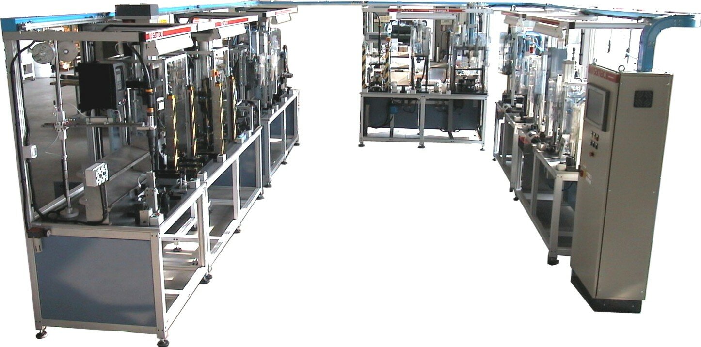
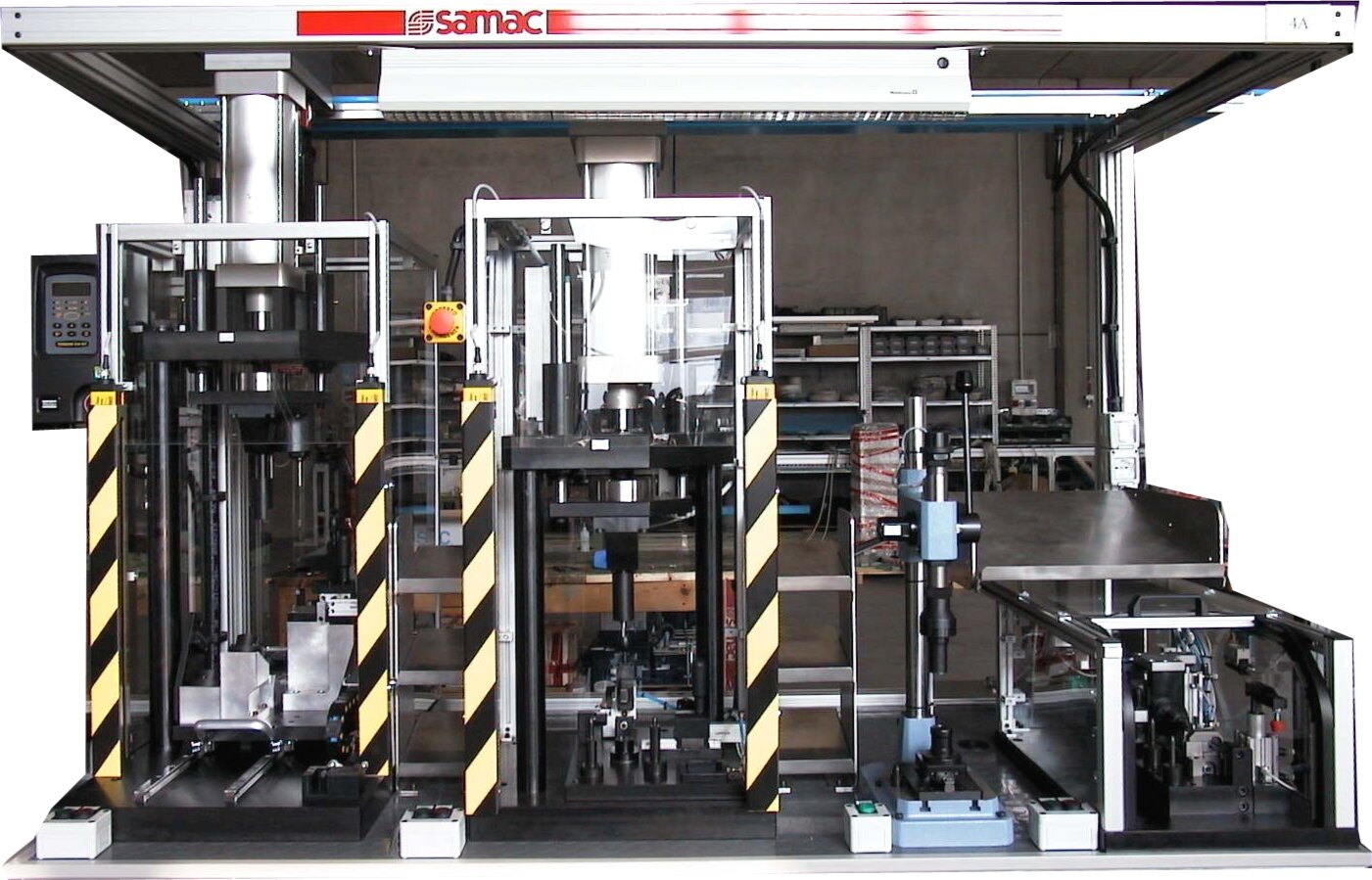
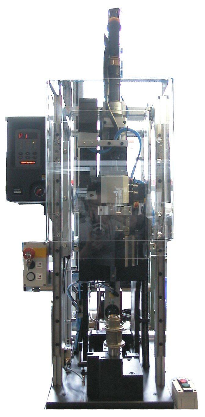
SEMIAUTOMATIC PLANT FOR CHANGE GEAR CONTROL VALVE ASSEMBLY
Technical Sheet
Photo Gallery
TELL US ABOUT YOUR PROJECT